Tungsten Carbide Dies: Custom Die Design, Material Grade & Common Failure Causes
Full Article Structure
- 1. Introduction: Application Value of Custom Tungsten Carbide Dies
- 2. Key Points for Tungsten Carbide Die Custom Design
- 3. Material Grade Selection for Tungsten Carbide Dies
- 4. Performance Reference Table for Carbide Die Common Grades
- 5. Main Common Failure Modes of Tungsten Carbide Dies
- 6. Root‑Cause Analysis of Typical Die Failures
- 7. Practical Preventive Measures Against Die Early Failure
- 8. Quick Reference Table for Die Problems & Countermeasures
- 9. Final Summary & Custom Technical Support
1. Introduction: Application Value of Custom Tungsten Carbide Dies
Tungsten carbide dies are critical tool components widely used in cold extrusion, metal stamping, wire drawing, nut forming and powder pressing industries. Compared with alloy‑steel dies, carbide dies deliver far higher hardness, wear resistance and compressive strength, greatly extending service life under high‑pressure cyclic forming conditions.
Most working scenarios cannot adopt off‑the‑shelf standard dies, so custom design becomes the mainstream solution. However, many purchasers encounter premature die failure such as rapid abrasive wear, edge chipping, radial cracking and surface pitting after putting custom carbide dies into production. The causes may come from unreasonable structural design, mismatched carbide grade, improper press‑fit tolerance, or unsuitable production process parameters.
This article explains core requirements for custom carbide die design, introduces grade‑matching rules for different forming loads, sorts out typical failure causes, and provides actionable improvement suggestions for die engineers, procurement specialists and mass‑production workshop supervisors. All technical content is based on practical cold‑forming production experience and ISO carbide material standards.
2. Key Points for Tungsten Carbide Die Custom Design
Good custom carbide die design must consider structural geometry, press‑fit interference, fillet transition, surface finish and stress distribution at the same time. Purely copying steel‑die geometry often leads to early fracture because carbide material has high compressive strength but low tensile resistance.
- Fillet and radius transition: Sharp inner corners produce serious stress concentration. All load‑bearing inner corners must adopt smooth fillet transition; avoid right‑angle inner edges as much as possible. Small‑radius sharp corners are the most frequent crack‑initiation positions for carbide dies.
- Press‑fit interference tolerance: Carbide die inserts are usually shrink‑fitted into steel outer sleeves. Too‑large interference will produce excessive pre‑compressive stress and cause die cracking before production; too‑small interference will lead to insert slipping, bouncing and uneven force during cyclic forming. Interference value needs to be calculated according to die outer‑inner diameter ratio and working pressure.
- Hole‑wall surface finish: For wire‑drawing and extrusion dies, high‑precision fine‑ground or polished inner holes reduce friction heat and material adhesion. Rough inner surfaces accelerate abrasive wear and material built‑up edge.
- Wall‑thickness proportion: Too‑thin carbide wall cannot bear huge radial forming pressure. Reasonable wall‑thickness ratio must be reserved in drawing design; excessively pursuing small‑size lightweight will greatly raise fracture risk.
- Exit‑angle and relief‑zone design: Reasonable working‑zone, compression‑zone and exit‑relief‑angle can lower friction force, reduce metal scratching and decrease thermal stress during continuous production.
When submitting custom drawings to suppliers, besides 2D dimension tolerances, you should clearly mark working pressure range, forming frequency, workpiece material and press‑fit requirements, helping technical teams optimize die structure instead of only processing pure geometric dimensions.
3. Material Grade Selection for Tungsten Carbide Dies
Carbide die grade selection is a balance between compressive‑wear resistance and impact‑toughness. High‑hardness low‑cobalt grades excel at anti‑abrasion performance, yet are sensitive to impact and tensile stress. High‑cobalt coarse‑grain grades gain better toughness to resist chipping and cracking, while sacrificing partial hardness and wear‑resisting capacity.
For continuous low‑impact wire‑drawing dies with abrasive metal materials, low‑cobalt fine‑grain carbide grades are preferred to pursue long‑term wear life. For cold‑extrusion nut‑forming dies bearing heavy cyclic impact, medium‑to‑high cobalt medium‑coarse grain grades should be selected to prevent sudden die cracking.
Special working conditions need special material adjustment. If the die contacts corrosive lubricant for long cycles, WC‑Ni nickel‑bonded carbide can be considered to resist chemical corrosion, though material cost will rise significantly. Most conventional cold‑forming projects still adopt WC‑Co cobalt‑bonded carbide series as the primary option.
Never simply select the hardest carbide grade for all die projects. Many custom dies fail quickly just because buyers blindly pursue maximum hardness without evaluating actual impact load and cyclic shock of the forming process.
4. Performance Reference Table for Carbide Die Common Grades
This table lists frequently‑adopted WC‑Co grades for carbide dies and corresponding typical application scenarios for drawing‑design reference.
| Carbide Grade | Cobalt Content | Grain Size | Main Feature | Typical Die Application |
|---|---|---|---|---|
| YG6 | 6% Co | Fine grain | High hardness, excellent wear‑resistance, low toughness | Fine wire drawing die, low‑impact static pressing die |
| YG8 | 8% Co | Medium grain | Balanced hardness and toughness, universal performance | General‑purpose wire drawing, light cold‑forming die |
| YG12 | 12% Co | Medium‑coarse grain | Good impact‑resistance, moderate wear performance | Nut cold extrusion, medium‑load stamping die |
| YG15 | 15% Co | Coarse grain | High transverse rupture strength, strong anti‑cracking ability | Heavy‑impact cold‑forging, high‑pressure forming dies |
Note: When the working environment contains corrosive lubricant, evaluate whether to switch to YN‑series WC‑Ni grades. Custom modified grades with trace alloy additives are available for special‑condition dies.
5. Main Common Failure Modes of Tungsten Carbide Dies
In actual mass‑production workshops, custom carbide dies mainly show four typical failure forms, which often appear alone or in combination.
- Abrasive wear: The inner working surface is gradually scratched and eroded by flowing metal material. Die hole dimension expands beyond allowable tolerance, and workpiece surface quality deteriorates. This belongs to normal service‑life consumption; abnormal rapid wear indicates grade mismatch or insufficient surface finish.
- Edge chipping & local spalling: Small pieces peel off from die‑hole inlet, outlet or fillet position. It is usually caused by cyclic impact, stress concentration or improper assembling pre‑stress.
- Radial / circumferential cracking: Visible cracks spread on carbide insert body. Once cracks generate, the die completely loses service capacity. Cracking mostly relates to excessive press‑fit interference, overload impact or design‑caused stress concentration.
- Surface pitting & corrosion: Tiny pits appear on die working surface, coming from chemical erosion by corrosive lubricant or cooling liquid. Pitting will accelerate wear and induce secondary micro‑cracks.
Distinguishing failure mode is the first step for troubleshooting. Same outward phenomena may result from completely different reasons including design, material, assembling and production parameters.
6. Root‑Cause Analysis of Typical Die Failures
When carbide dies fail prematurely, you need to check from four dimensions: custom design, carbide material, assembling press‑fit, and on‑site production parameters.
If rapid abrasive wear occurs while no chipping or cracking appears, the most possible reasons are: adopting too‑high‑cobalt soft grade for abrasive workpiece material; insufficient inner‑hole polishing finish; poor lubrication condition on production line.
If local edge spalling and chipping happen: sharp stress‑concentrating corners in die geometry; insufficient toughness of selected carbide grade; unbalanced impact load during forming cycle; foreign hard impurities mixed into workpiece material.
For sudden whole‑body cracking of carbide inserts: over‑large shrink‑fit interference value; uneven stress from mis‑alignment during installation; excessive instantaneous forming pressure exceeding material compressive limit; original micro‑cracks existing inside carbide blank from sintering process.
For surface pitting corrosion failure: long‑term contact between carbide die and acid‑containing lubricant; cobalt binder phase is corroded, causing surface structure loose. In such case WC‑Ni material or surface coating solution should be considered.
7. Practical Preventive Measures Against Die Early Failure
Combined with above root‑cause analysis, factories can take multi‑layer preventive measures to extend custom carbide die service life.
- Optimize drawing design: remove sharp inner corners, adopt reasonable fillet radius, calculate press‑fit interference according to working pressure, keep enough carbide wall‑thickness, optimize working‑zone and exit‑angle structure.
- Select matching carbide grade: prioritize low‑cobalt fine‑grain for wear‑dominated stable continuous forming; choose medium‑high cobalt coarse‑grain grade for impact‑dominated cyclic cold‑forging working conditions.
- Control assembling quality: strictly follow calculated interference for shrink‑fit; guarantee coaxiality during installation to avoid partial overload stress; prohibit violent knocking on carbide insert during mounting.
- Manage production‑site conditions: keep good lubrication and cooling; filter metal scraps and hard impurities in raw material; avoid long‑time contact between carbide die and corrosive lubricant; control peak instantaneous forming pressure within material allowable range.
- Incoming quality inspection: require suppliers to provide hardness, density and TRS test reports for each batch of carbide die blanks, to exclude blanks with internal hidden micro‑defects.
8. Quick Reference Table for Die Problems & Countermeasures
This table helps engineers quickly locate problems and formulate improvement plans for failed carbide dies.
| Failure Phenomenon | Primary Suspected Causes | Recommended Improvement Measures |
|---|---|---|
| Fast abrasive wear, dimension out‑of‑tolerance | Tough grade over‑selected; poor inner‑hole finish; bad lubrication | Switch to lower‑cobalt grade; improve hole polishing; optimize lubricant system |
| Local edge chipping and spalling | Sharp fillet; insufficient toughness grade; cyclic impact load | Increase fillet radius; raise cobalt content of carbide grade; stabilize forming impact |
| Carbide insert body cracking | Excessive shrink‑fit interference; mis‑alignment assembly; overload pressure | Recalculate press‑fit interference; improve mounting coaxiality; limit peak forming pressure |
| Surface pitting & corrosion pits | Corrosive lubricant erodes cobalt binder phase | Replace anti‑corrosion lubricant; adopt WC‑Ni grade or surface coating treatment |
9. Final Summary & Custom Technical Support
The service performance of custom tungsten carbide dies depends on three core factors: reasonable custom structural design, correctly‑matched carbide material grade, and standardized assembling plus on‑site production management. High‑quality carbide material cannot compensate defects from unreasonable drawing design; meanwhile perfect geometry design will also fail if the carbide grade mismatches actual load conditions.
Common premature‑failure modes include abrasive wear, edge chipping, body cracking and surface corrosion. When die problems appear, classify failure phenomena first, then trace root causes among design, material, assembly and process parameters, instead of simply replacing dies with the same specifications repeatedly.
Our technical team supports full‑range custom tungsten carbide die development. We can participate in drawing review, grade recommendation and parameter suggestion according to your forming‑process requirements, helping you reduce early‑failure risk for custom carbide dies.
Custom Tungsten Carbide Die Products & Service
OEM / ODM Custom Carbide Dies
Custom‑manufacture various carbide wire‑drawing dies, cold extrusion dies, stamping and pressing dies according to customer technical drawings. Support grade customization, inner‑hole high‑precision polishing and special surface treatment.
Learn More → /custom‑carbide‑blanks.htm
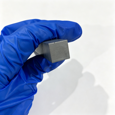
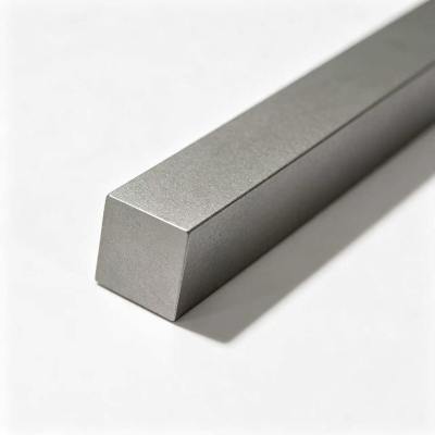
Carbide Blank for Die‑Making
Supply standard and pre‑machined carbide die blanks in multiple WC‑Co grades, for customer secondary die‑processing operations.
CTA Contact Zone
Custom Drawing Review & Technical Consultation
📧 Contact Us → /contact‑us.htm
Submit your die drawings, forming pressure, workpiece material and working‑condition description. Obtain free carbide‑grade suggestion and custom‑process evaluation.
Bulk Procurement & Distributor Partnership
📧 Contact Us → /contact‑us.htm
Wholesale quotation for carbide dies and die blanks for industrial buyers and distributors, support long‑term mass‑production supply contracts.
Disclaimer
The information provided in this article is for general reference purposes only. Actual carbide die service life is comprehensively affected by die‑structure, press‑fit tolerance, workpiece material, lubrication, forming pressure and equipment status. Please consult our technical team for application‑specific suggestions before bulk custom‑die orders. All material‑performance data are based on standard industrial laboratory test conditions.